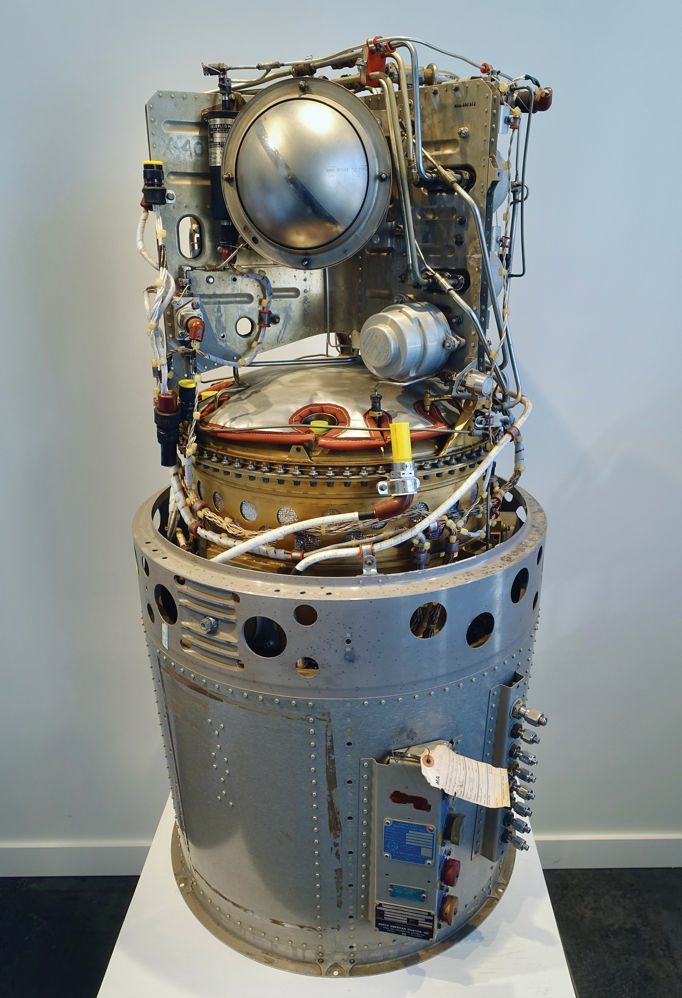
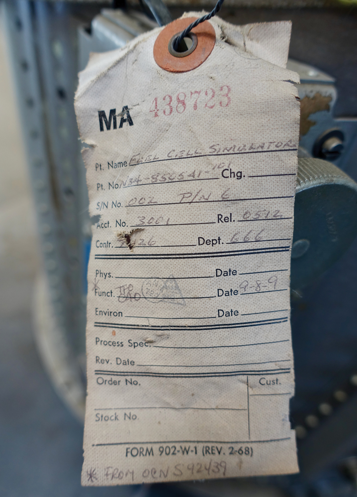
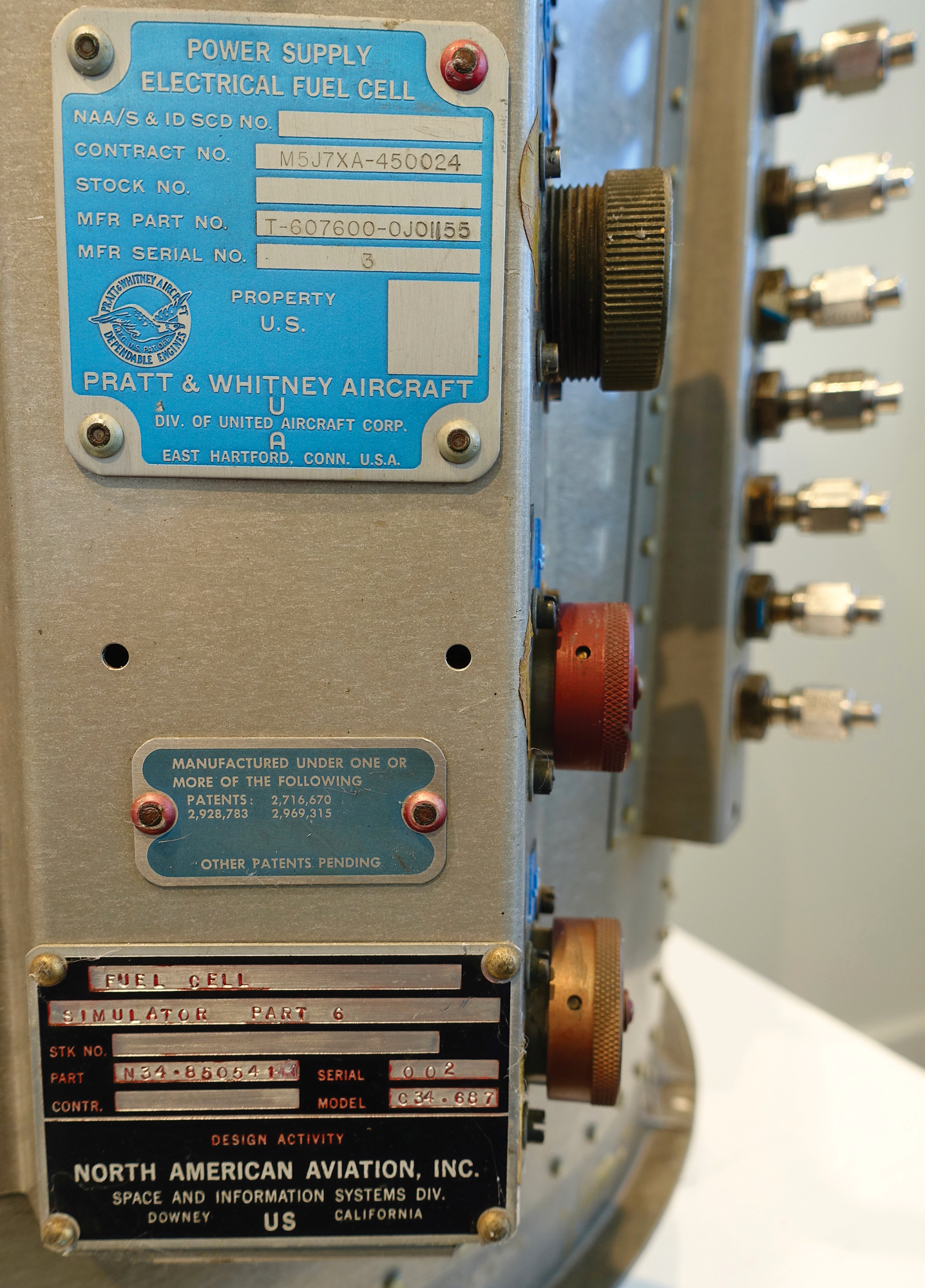
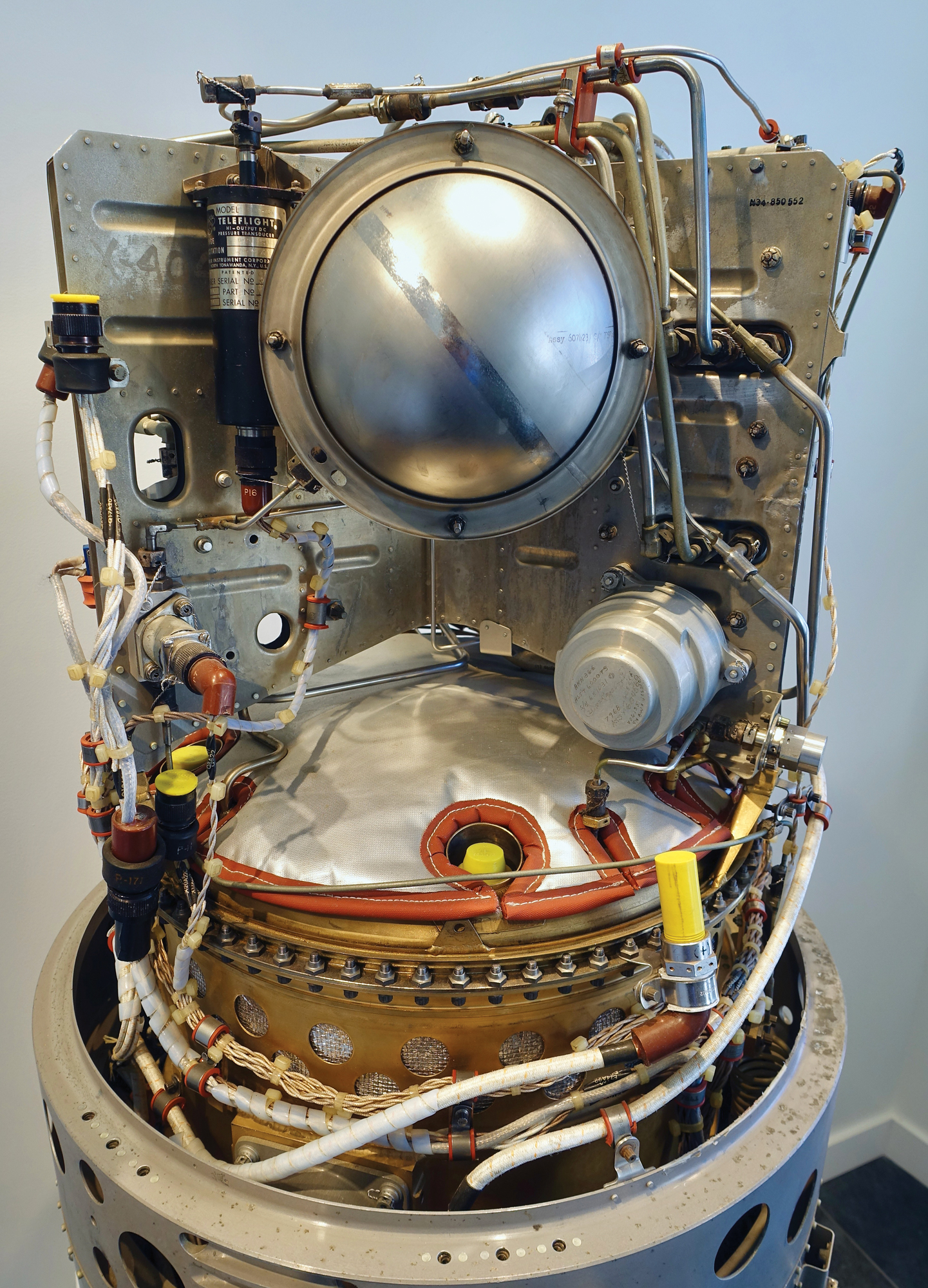
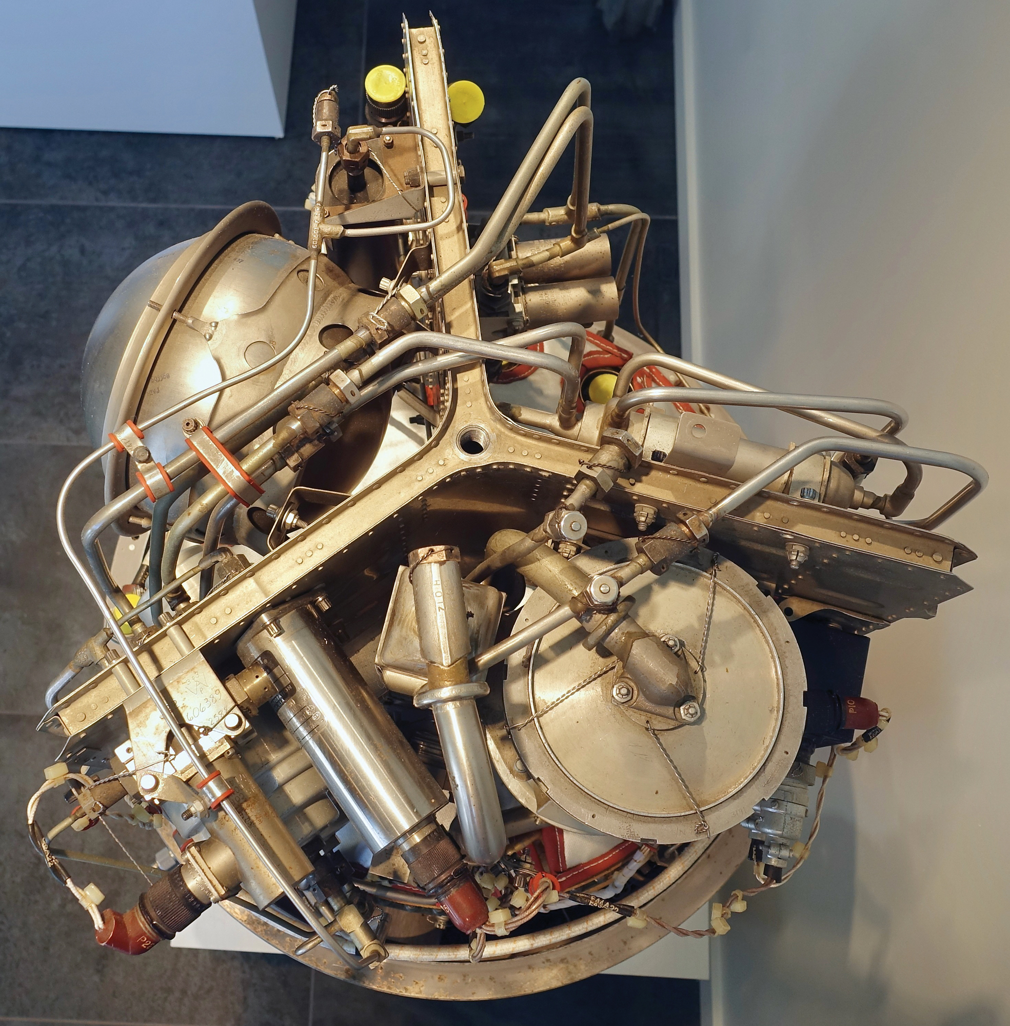
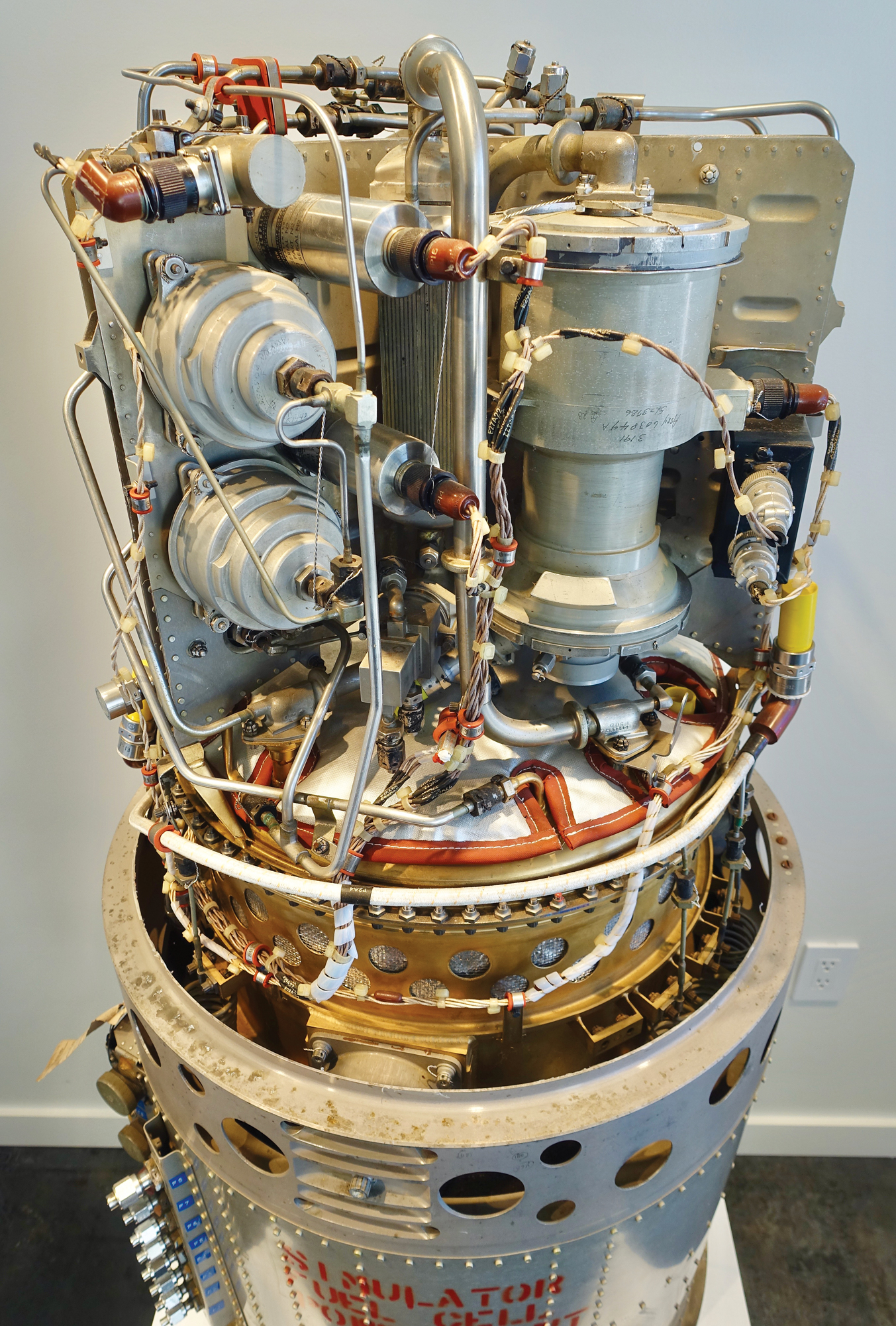
Apollo CSM Fuel Cell Serial Number 3, one of the triad used in the Ground Testing Simulator to test all of the electrical systems in development for Apollo. With electrical and liquid oxygen and hydrogen connectors on the side panel, the unit measures 22” in diameter and 43” tall, with a weight of approximately 200 lbs. Manufactured by Pratt & Whitney Aircraft Corp under subcontract for North American Aviation. This particular fuel cell is Serial Number 3 from the simulator, with a Feb 1968 edition part tag with a functional test noted for 9/8/69. It is identical to the flight unit, but with additional simulator functionality and interfaces. Having a power source similar to the flight item was essential to test all of the other electrical systems for Apollo. Red letters on the side read “Simulator Fuel Cell Powerplant.”
This fuel cell has been modified with a simulator interface to replicate/check some of the mechanical, electrical and fluid exchanges between the powerplant and the rest of the CSM Environmental Control System (ECS), otherwise it’s identical to flight. This configuration is what is currently on display at national institutions (Smithsonian NASM, New Mexico Museum of Space History and the USSRC). Its function was as part of a Fuel Cell simulator package used to validate that the Service Module interfaces were properly functional (control, power, reactants, water output) at North American prior to installation of the flight fuel cells. This piece will be crated and shipped from California; the buyer is responsible for all associated costs.
One of the primary technology developments during Apollo concerned the electrical systems, and they became a focal point of the Apollo 13 rescue mission, from the explosion in the Service Module fuel cell oxygen tank to the resulting need to conserve energy and shift to the LM as a lifeboat.
One interesting technology development that started in the Gemini program, with an eye to the needs of the Apollo spacecraft, was the electric fuel cell. This is a vintage Apollo Fuel Cell Power Plant. It's not only critical enabling technology for Apollo but also the first instantiation of a practical Alkaline Fuel Cell and a progenitor for fuel cell technology to follow.
The three fuel cell power plants in the Service Module combined hydrogen and oxygen to generate electricity onboard. The waste stream of the fuel cell is pure water, which was used for consumption by the crew.
On the inside are 31 individual fuel cells, connected in series, which operate at 27 to 31 volts. Normal power output is 563 to 1420 watts, with a maximum of 2300 watts. Primary construction materials are titanium, stainless steel, and nickel.
Here are some descriptive passages from How Apollo Flew to the Moon, 2011, p.185:
“The adoption of the fuel cell in Apollo killed two design quarries with one stone. Not only did it produce lashings of electricity, the water it produced became a sort of lifeblood of the spacecraft. It quenched the thirst of the crew and rehydrated their food in metered amounts through a pistol-style squirt gun on the end of a hose. It also supplemented the cooling of the spacecraft’s electronic equipment by being evaporated into space, taking heat with it.
Although it could reach efficiencies of 70%, the reaction still yielded significant amounts of heat. Some of this was used to warm the extremely cold reactants before they entered the cell; the rest was rejected through eight radiator panels around the upper circumference of the service module.
Apollo 13’s oxygen tank explosion notwithstanding, no Apollo flight suffered from a failure of their fuel cells.
Among the limitations of the Apollo fuel cell was that it was very sensitive to presence of impurities in the reactants. Even with hydrogen and oxygen of the highest purity that NASA could procure, the build-up of contaminants required that the cells be purged from time to time to avoid the resultant loss of electrical power. Oxygen purges were carried out daily, while hydrogen purges occurred every second day.
The fuel cells had a limited range of output power. They could not deliver more than 1.4 kilowatts at any one time, yet their power output had to be maintained above 400 watts at all times. The spacecraft’s requirements were much more variable, especially when the motors had to operate. Batteries were a way of smoothing out the load on the fuel cells because they could provide extra power in the peaks of demand. At other times, their need to be recharged provided a convenient load for the fuel cells. At the end of the mission, the batteries were all that remained to power the CM as it streaked through the atmosphere during reentry. They were therefore essential!
The CM carried a total of five silver oxide zinc batteries mounted in the lower equipment bay below the navigation instruments. This battery technology had the highest energy to weight ratio at the time.
Apollo 12 relied on the CM batteries when its lightning strike incident took the fuel cells offline for most of the ascent to orbit."
Technical Details:
Each of the assemblies measures 44 inches high, 22 inches in diameter, and weighs 245 pounds; and were designed for installation in Sector (Bay) 4 of the SM. Primarily constructed of titanium, stainless steel, and nickel, the Fuel Cells are rated at 27 to 31 volts under normal loads. There are 31 separate cells in a stack, each producing 1 volt, with potassium hydroxide and water as electrolyte. Each cell consists of a hydrogen and an oxygen electrode, a hydrogen and an oxygen gas compartment and the electrolyte. Each gas reacts independently to produce a flow of electrons. The fuel cells are nonregenerative. They are normally operated at 400 degrees F with limits of 385 and 500 degrees. Water-glycol is used for temperature control. The fuel cells use hydrogen, oxygen, and nitrogen under regulated pressure to produce power and, as a by-product, water. Detailed discussion of functionality is addressed in the following paragraphs.
The Bacon-type fuel cell powerplant, was configured in a cluster of 3 systems to comprise the CSM power plant; each cell individually coupled to a heat rejection (radiator) system, the hydrogen and oxygen cryogenic storage systems, a water storage system, and a power distribution system. The powerplants generate DC power on demand through an exothermic chemical reaction. A byproduct of this chemical reaction is water, which is fed to a potable water storage tank in the Command Module (CM) where it is used for astronaut consumption and for cooling purposes in the environmental control subsystem. The amount of water produced is proportional to the ampere-hours.
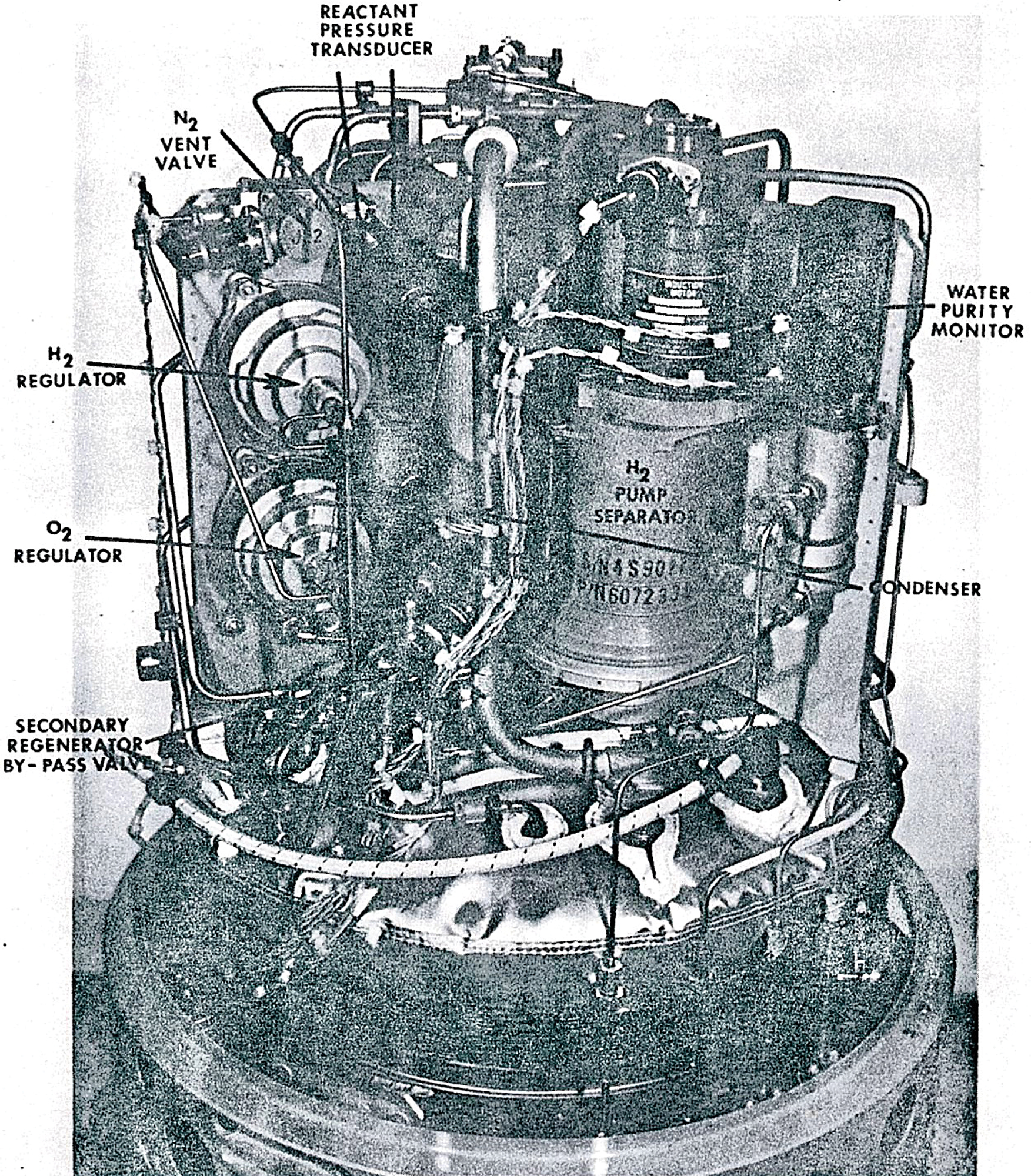
The water separation, reactant control, and heat transfer components are mounted in a compact accessory section attached directly above the pressure jacket. Powerplant temperature is controlled by the primary (hydrogen) and secondary (glycol) loops. The hydrogen pump, providing continuous circulation of hydrogen in the primary loop, withdraws water vapor and heat from the stack of cells. The primary bypass valve regulates flow through the hydrogen regenerator to impart exhaust heat to the incoming hydrogen gas as required to maintain the proper cell temperature. The exhaust gas flows to the condenser where waste heat is transferred to the glycol, the resultant temperature decrease liquifying some of the water vapor. The motor-driven centrifugal water separator extracts the liquid and feeds it to the potable water tank in the CM. The temperature of the hydrogen-water vapor exiting from the condenser is controlled by a bypass valve which regulates flow through a secondary regenerator to a control condenser exhaust within desired limits. The cool gas is then pumped back to the fuel cell through the primary regenerator by a motor-driven vane pump, which also compensates for pressure losses due to water extraction and cooling. Waste heat, transferred to the glycol in the condenser, is transported to the radiators located on the fairing between, the CM and SM, where it is radiated into space. Radiator area is sized to reject the waste heat resulting from operation in the normal power range. If an emergency arises in which an extremely low power level is required, individual controls can bypass three of the eight radiator panels for each powerplant. This area reduction improves the margin for radiator freezing which could result from the lack of sufficient waste heat to maintain adequate glycol temperature. This is not a normal procedure and is considered irreversible due to freezing of the bypassed panels. Reactant valves provide the connection between the powerplants and the cryogenic system. They are opened during pre-launch fuel cell startup and closed only after a powerplant malfunction necessitating its isolation from the cryogenic system. Before launch, a valve switch is operated to apply a holding voltage to the open solenoid of the hydrogen and oxygen reactant valves of the three powerplants. This voltage is required only during boost to prevent inadvertent closure due to the effects of high vibration. The reactant valves cannot be closed with this holding voltage applied. After earth orbit insertion, the holding voltage is removed and three circuit breakers are opened to prevent valve closure through inadvertent activation of the reactant valve switches.
Nitrogen is stored in each powerplant at 1500 psia and regulated to a pressure of 53 psia. Output of the regulator pressurizes the electrolyte in each cell through a diaphragm arrangement, the coolant loop through an accumulator, and is coupled to the oxygen and hydrogen regulators as a reference pressure. Cryogenic oxygen, supplied to the powerplants at 900 +/- 35 psia, absorbs heat in the lines, absorbs additional heat in the fuel cell powerplant reactant preheater, and reaches the oxygen regulator in a gaseous form at temperatures above 0 degrees F. The differential oxygen regulator reduces pressure to 9.5 psia above the nitrogen reference, thus supplying it to the fuel cell stack at 62.5 psia. Within the porous oxygen electrodes, the oxygen reacts with the water in the electrolyte and the electrons provided by the external circuit to produce hydroxyl ions. Cryogenic hydrogen, supplied to the powerplants at 245 (+15, -20) psia, is heated in the same manner as the oxygen. The differential hydrogen regulator deduces the pressure to 8.5 psia above the reference nitrogen, thus supplying it in a gaseous form to the fuel cells at 61.5 psia. The hydrogen reacts in the porous hydrogen electrodes with the hydroxyl ions in the electrolyte to produce electrons, water vapor, and heat. The nickel electrodes act as a catalyst in the reaction. The water vapor and heat are withdrawn by the circulation of hydrogen gas in the primary loop and the electrons are supplied to the load.
Each of the 31 cells contains electrolyte which on initial fill consists of approximately 83 percent potassium hydroxide (KOH) and 17 percent water by weight. The powerplant is initially conditioned to increase the water ratio, and during normal operation, water content will vary between 23 and 28 percent. At this ratio, the electrolyte has a critical temperature of 360 degrees F. Powerplant electrochemical reaction becomes effective at the critical temperature. The powerplants are heated above the critical temperature by ground support equipment. A load on the powerplant of approximately 563 watts is required to maintain it above the normal minimum operating temperature of 385°F. The automatic in-line heater circuit will maintain powerplant temperature in this range with smaller loads applied.
This piece will be crated and shipped from California; the buyer is responsible for all associated costs.
We use cookies on this site to improve your experience. By using this site, you accept our use of cookies. To learn more, please see our Privacy Policy.